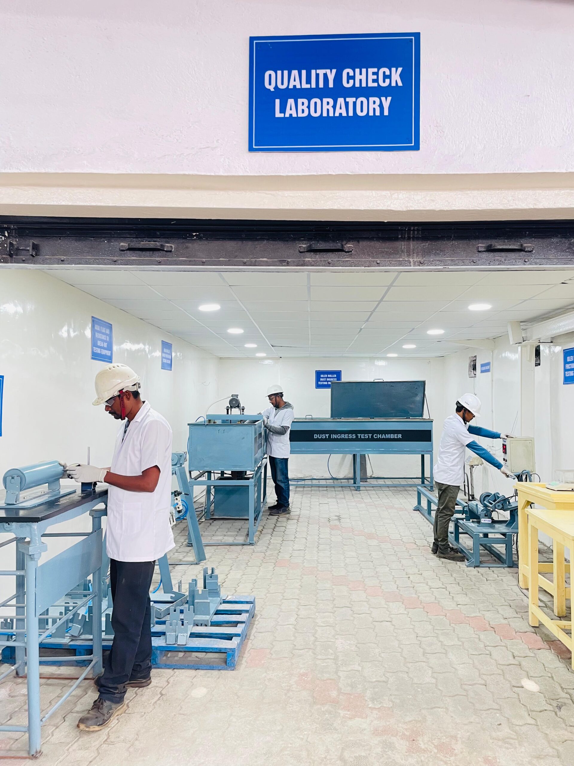
QUALITY CONTROL
Our commitment to excellence is reflected in our rigorous quality control processes, which are designed to uphold the integrity of every product we manufacture. Whether it’s our idler rollers, conveyor systems, or other components, we ensure that each product is subjected to comprehensive testing and inspection to meet or exceed industry specifications.
We operate a state-of-the-art quality control lab staffed by experts and equipped with advanced testing technology. Committed to excellence, we ensure precision, reliability, and compliance, delivering results that exceed industry standards and customer expectations.
RADIAL RUN-OUT TEST
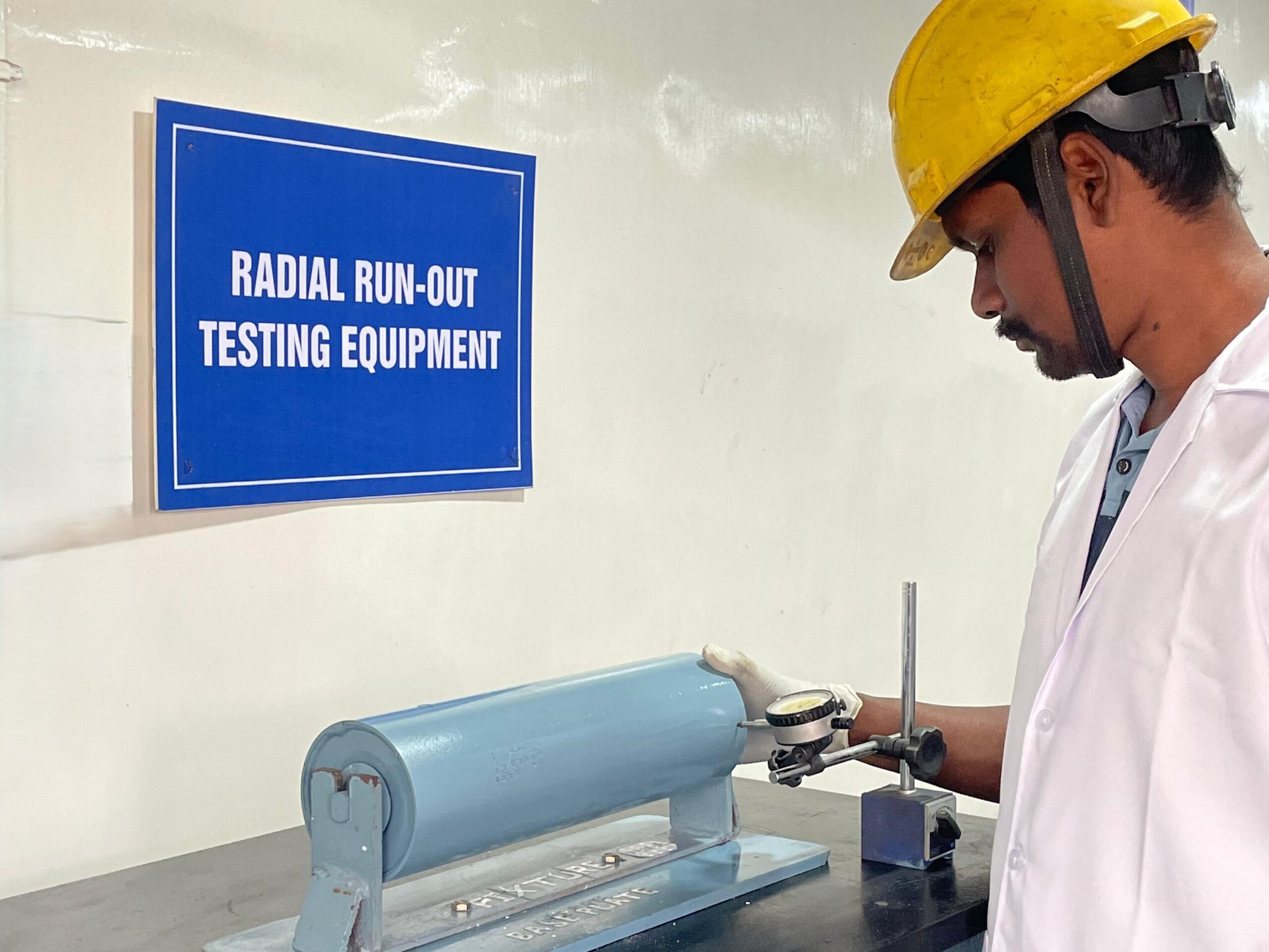
The Radial Runout Test for idler rollers measures the deviation of the roller’s outer surface from a true circular path during rotation. This test ensures that the roller’s shell remains concentric with the shaft, minimizing vibration, uneven wear, and misalignment in conveyor belt systems.
Purpose of the Test:
To verify the concentricity and straightness of the idler roller.
To identify defects like bending of the shaft, improper assembly, or shell deformation.
To ensure smooth conveyor belt operation and minimize energy loss caused by roller irregularities.
AXIAL FLOAT & RESISTANCE TO PRESS OUT TEST
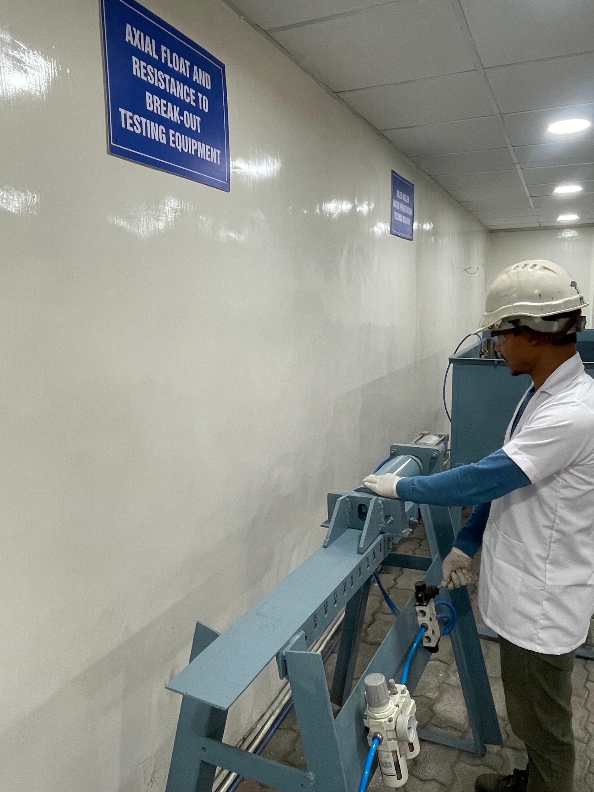
The Axial Float Test for idler rollers evaluates the amount of lateral movement (axial play or float) of the roller shell along the axis of the shaft. This test is crucial to ensure that the axial movement is within acceptable limits, preventing misalignment, noise, or damage during operation. This test assesses the fit between the roller shell, bearings, and shaft confirming that the roller operates smoothly without excess lateral movement that could cause belt misalignment or uneven wear.
In the Resistance to Press Out Test, the individual components of the Idler Roller shall be assembled such a way that they shall not separate when a load of 15 KN is applied axially to the shaft in both directions. The welding design and workmanship shall be adequate enough that no visible sing of weld rapture should take place under the above load.
WATER INGRESS TEST
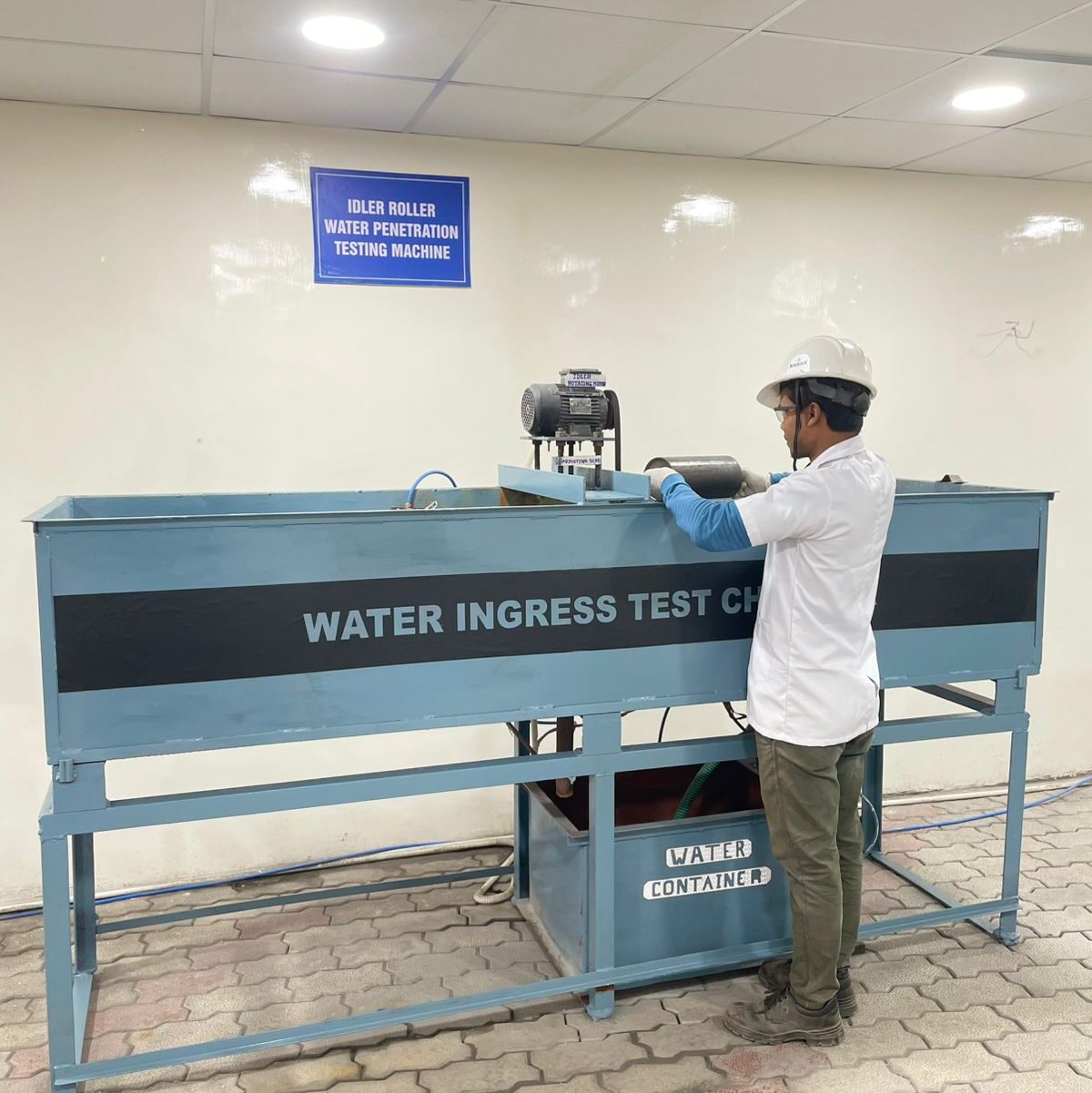
Selected roller is mounted on a suitable fixture, on a test rig located on a closed dust chamber, roller shall be operated at operating speed while maintaining a continuous while maintaining continuous spray of water directly on the roller face near the rain cap at 45º angle with a pressure of 1 Kg/cm2 . After a period of 180 minutes. the roller s shall be stopped & dismantled to check for water particles at the bearing area. No water contamination / emulsification of grease / water droplets are acceptable
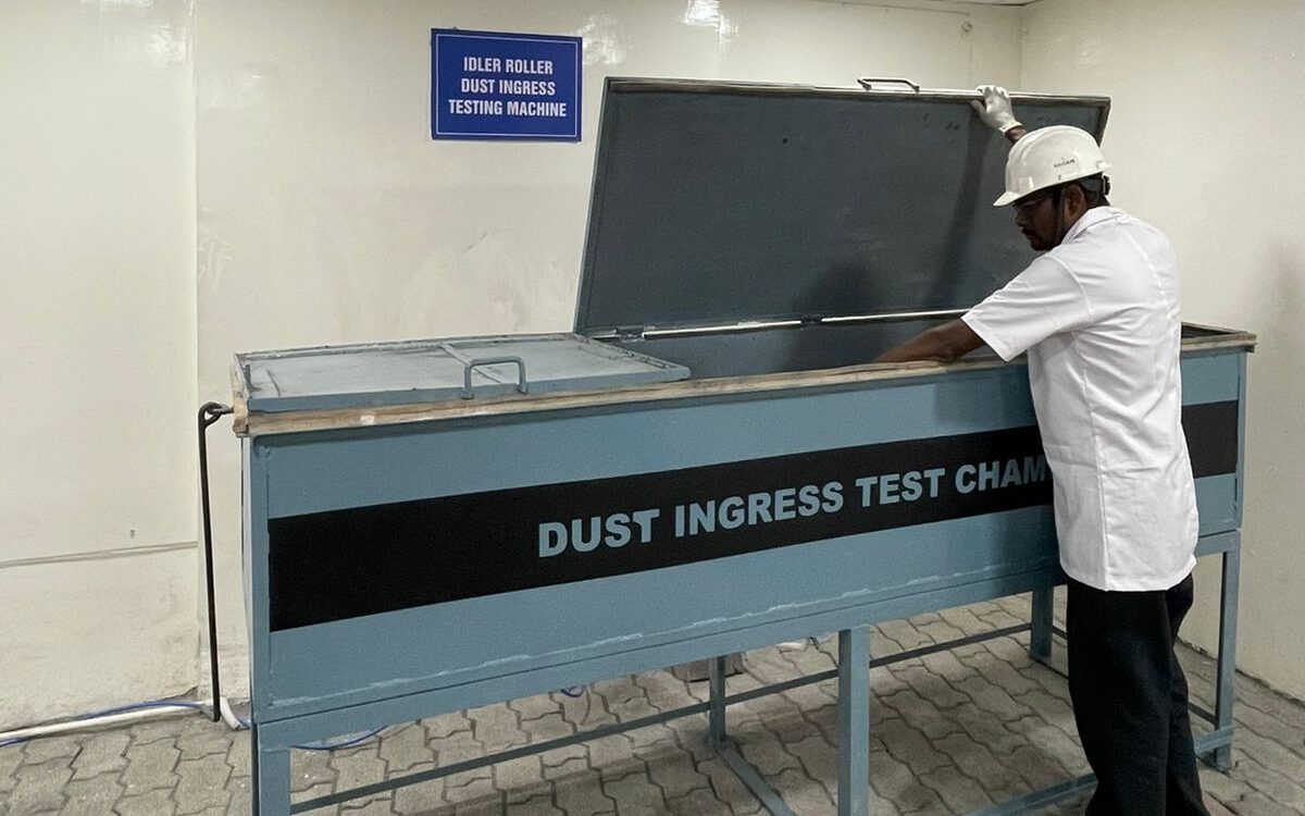
DUST INGRESS TEST
Selected roller is mounted on a suitable fixture, on a test rig located on a closed dust chamber, roller shall be operated at operating speed while maintaining a continuous dust cloud in the dust chamber. After 180 minutes the roller shall be stopped and shall be dismantled. Grease from the vicinity of the bearing shall be collected & dissolved in a suitable solvent. The residue shall be measured & compared with residue of fresh grease. The difference between the two should be within 5% for acceptance.
FRICTION FACTOR TESTING MACHINE
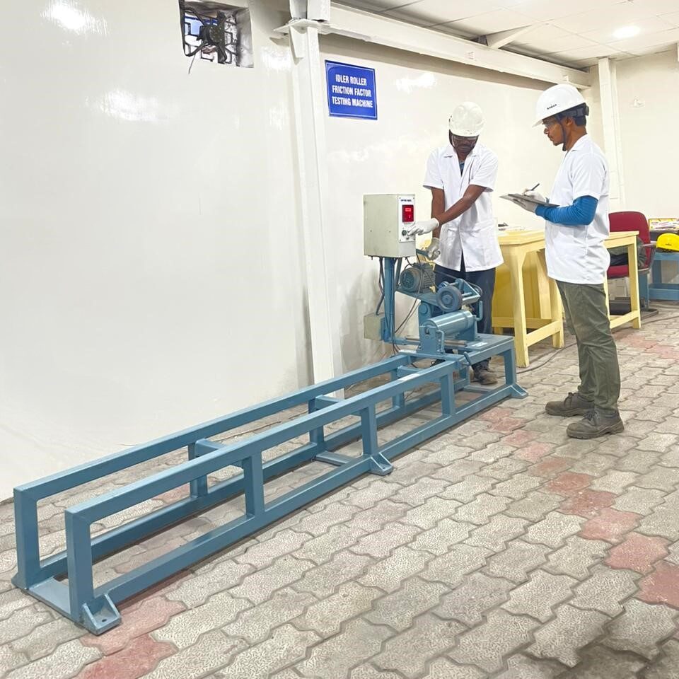
Friction Factor Testing Equipment provided with digital read-out for measuring the speed of rotation and the time it takes to come to stationary position. A fabricated M.S. stand with arrangement to mount idlers of different sizes is provided. Rubberized roller driven by a is pressed against the Idler to be tested, making it to rotate. After the Idler attains a steady speed which is indicated in the RPM meter, the rubber roller is
moved backward manually removing the drive to the Idler under testing. The Idler now rotates on its own and slowly the speed reduces and it becomes zero. The moment the slide is moved backward disconnecting the Idler under testing with the rubberized roller, the RPM meter indicates the manner in which the speed is going down and a timer in the RPM meter is switched on simultaneously showing the time lapse. The moment the rotation of the Idler is zero, the timer stops. The arrangement indicates the
final speed and the time it takes for the speed to come to zero. With the help of empirical formula, the friction factor is calculated.
 using WordPress and